Brushless Motor Controller Circuit Diagram
On the other hand, brushless motors (also known as BLDC motors, see Fig. 2) are made without any brushes; the internal coils are energized by a special circuit known colloquially as an ESC (or Electronic Speed Controller). They are now found in many different types of devices, large and small, from commercially available drones to electric cars.
Updated Brushless controller schematic 2015 « Brushless motors, 3Phase inverters, schematics
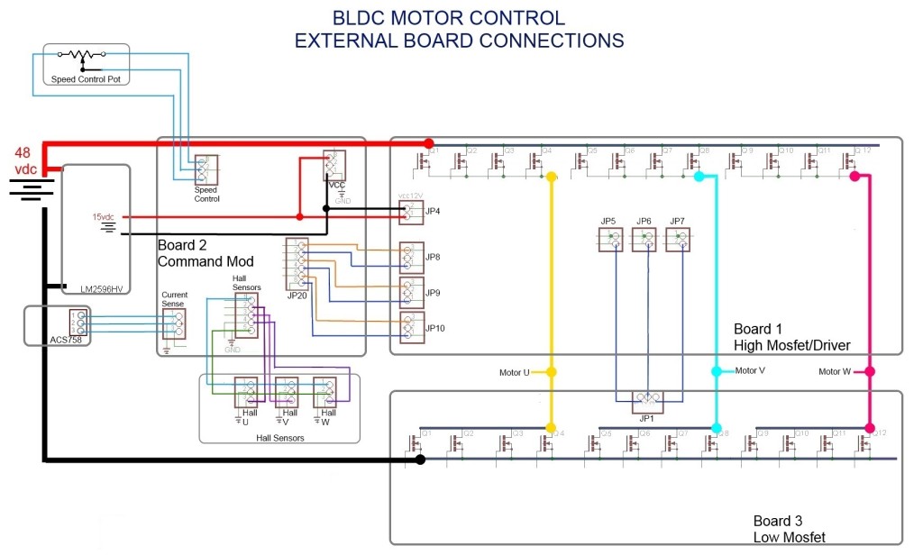
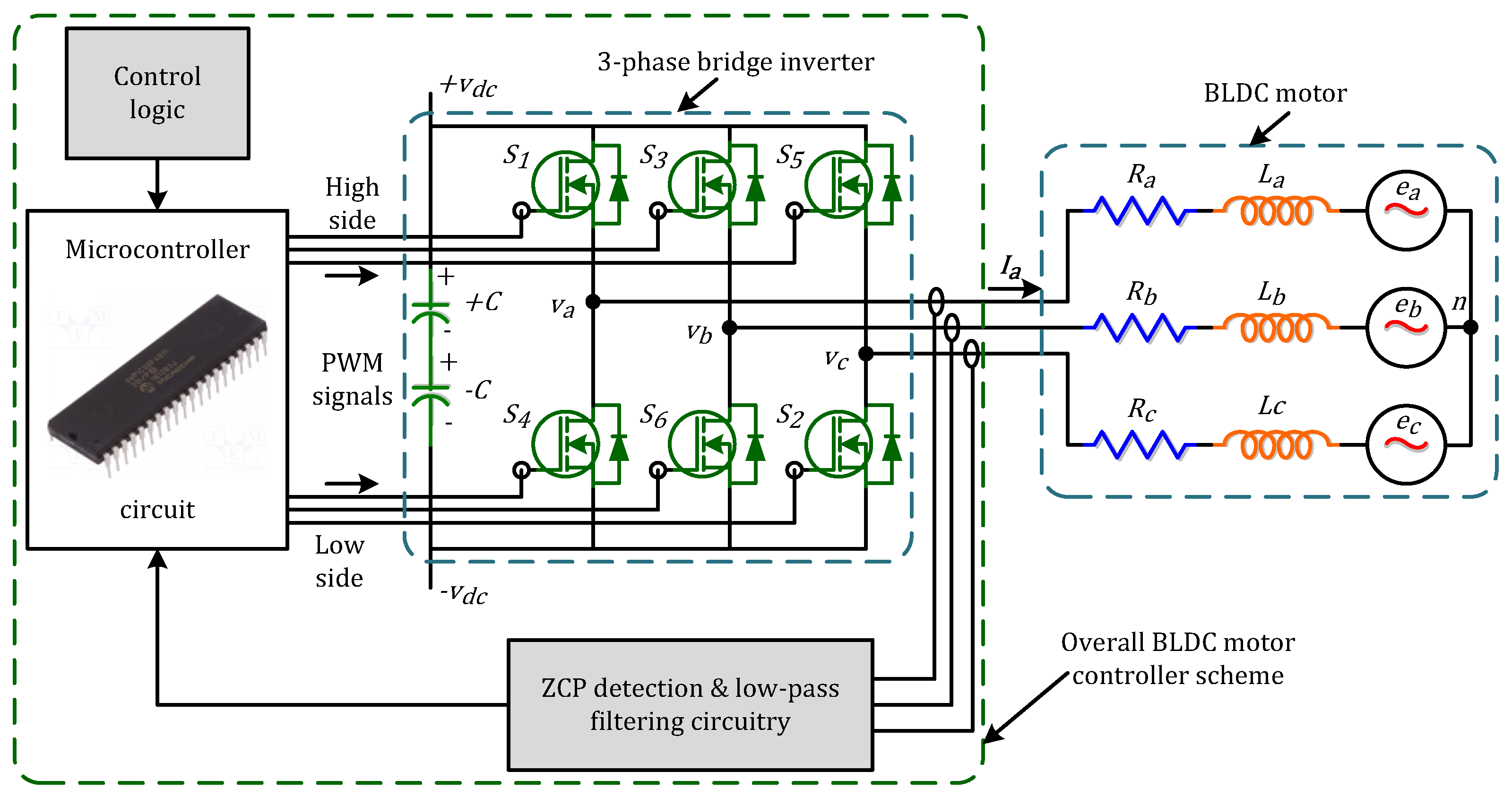
An ESC or an Electronic Speed Controller controls the brushless motor movement or speed by activating the appropriate MOSFETs to create the rotating magnetic field so that the motor rotates.

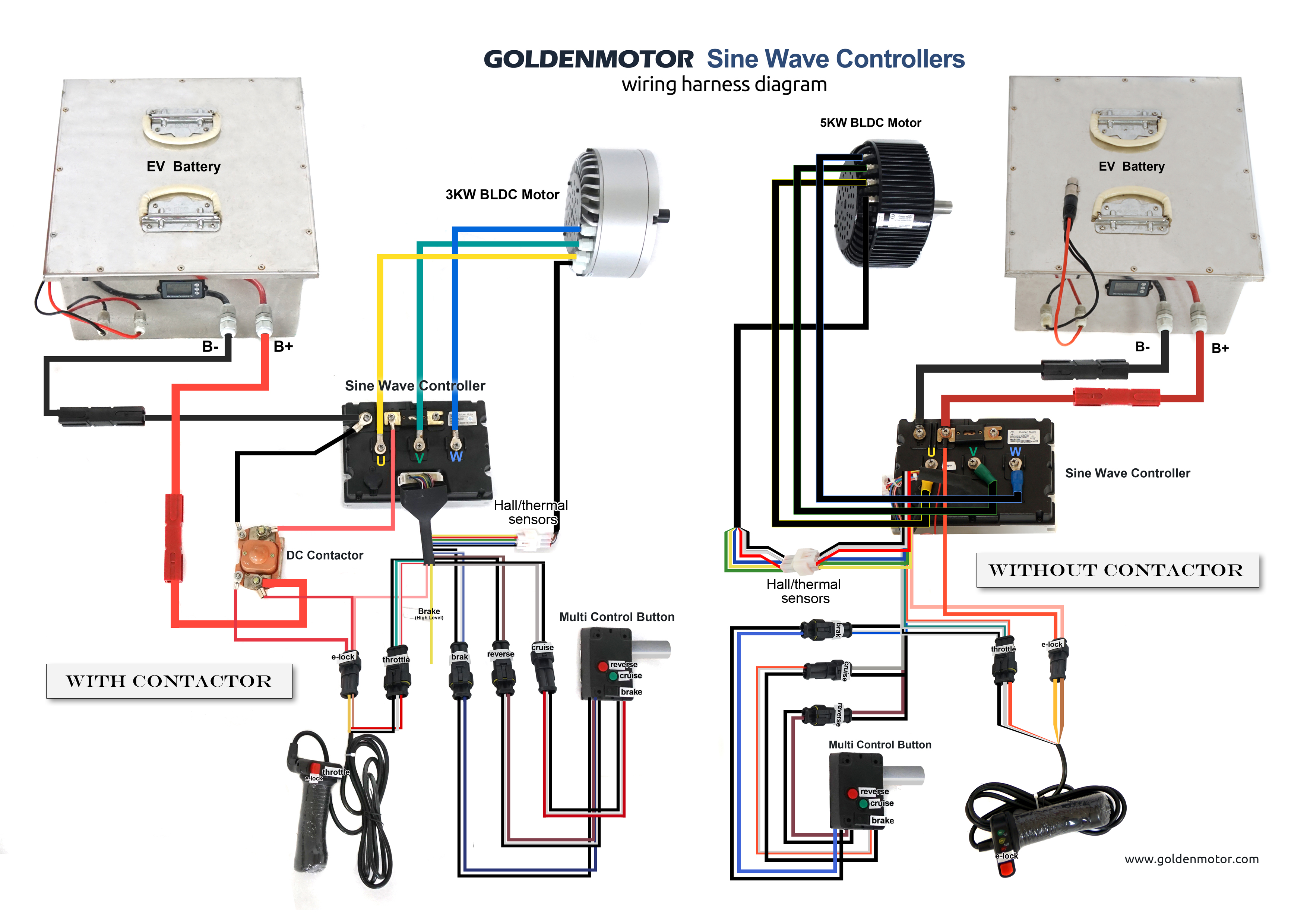
brushless controller wiring guide Wiring Diagram
A BLDC motor is known as a "synchronous" type because the magnetic field generated by the stator and the rotor revolve at the same frequency. One benefit of this arrangement is that BLDC motors do not experience the "slip" typical of induction motors.
[DIAGRAM] Dc Motor Controller Schematic Diagram
In this project article, we're going to be taking a different approach to my typical project. Driving a brushless motor is relatively simple from a schematic perspective; however, there is a large amount of theory about brushless direct current motors that you need to understand to be successful. If you only have experience with brushed motors or no experience with driving motors at all, we.

Hub Motor Controller Circuit Diagram
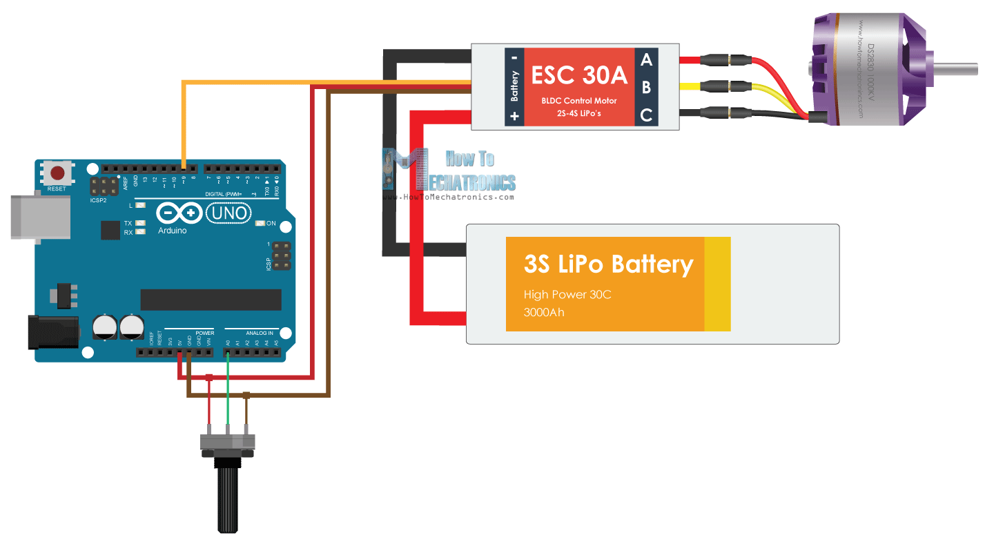
The HIN lines of the three IR2101 are connected to pins 11, 10 and 9 respectively for phase A, phase B and phase C. The Arduino UNO can generate PWM signals on that pins where only high side mosfets are PWMed. The code below does not use any BLDC motor library. As mentioned above, Arduino pins 9, 10 and 11 can generate PWM signals where pin 9.

işlem Yağlamalamak servet bldc motor driver circuit diagram sorti BağıĢık Tarihi geçmiş
The brushless DC (BLDC) motor's increasing popularity is due to the use of electronic commutation. This replaces the conventional mechanics comprised of brushes rubbing on the commutator to energize the windings in the armature of a DC motor.

vizual Poate rezista caligrafie brushless motor controller schematic patru paranteză prezentare
A BLDC motor controller regulates the speed and torque of the motor; it can also start, stop, and reverse its rotation. To understand the working principles of the controller, let us start first with the construction of a brushless motor. Its major components comprise: an armature or rotor made of permanent and in many cases neodymium magnets; and

Bldc Motor Control Circuit Diagram Datasheet Pdf Diagram Circuit
In this post we learn how to make a simple 3 phase brushless DC motor driver circuit. The circuit employs the popular IRS2330 3-phase driver IC
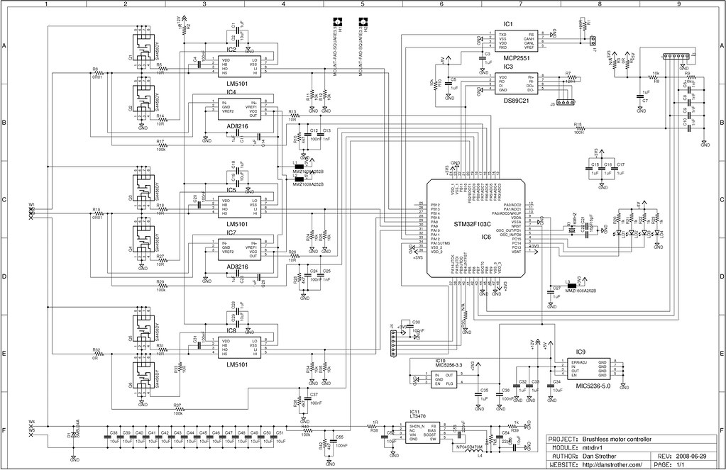
Brushless motor controller schematic Dan Strother Flickr
Brushless DC (BLDC) motors are a type of electric motor that operates on the principles of electromagnetism. They are commonly used in applications requiring precise control, high efficiency, and low maintenance. Unlike traditional brushed DC motors, BLDC motors do not have a physical commutator and brushes.

Brushless Gimbal Controller Schematic
Then using the write () function we send the signal to the ESC, or generate the 50Hz PWM signal. The values from 0 to 180 correspond to the values from 1000 to 2000 microseconds defined in the setup section. So, if we upload this code to our Arduino, and then power up everything using the battery, then we can control the speed of the brushless.
Wiring Diagram Brushless Motor Esc Wiring Diagram
78 Hi, I just finished a new controller for my electric scooter project. The current is limited to 50Amp but it can sustain at least 80Amp. It is also based on Mc33035 IC and it is capable to decode signal from the hall sensors. Now i`m also building a new Go kart controller.I will use the same logic board as the scooter.

48v Brushless Motor Controller Wiring Diagram
Brushless DC (BLDC) motors have become extremely popular over their predecessor, the brushed DC motor (see figure below). As the name implies, "brushed" DC motors use brushes, and a commutator, for controlling the movement of the motor's rotor. Figure 1. Brushed DC motors use brushes and a commutator. Image courtesy of Clemson University.

Brushless motor controller Schematic « Brushless motors, 3Phase inverters, schematics
The procedure for developing a fixed stator electromagnet and a rotating free magnetic rotor guarantees improved effectiveness to BLDC motors in comparison to the traditional brushed motors which have precisely the opposite topology thereby desire brushes for the motor operations.
Revizuire Nesatisfăcător terminat brushless dc motor controller schematic război Probleme
Brushless DC Motor Control Made Easy. AN857 DS00857A-page 2 2002 Microchip Technology Inc. In this example there are three electromagnetic circuits connected at a common point. Each electromagnetic circuit is split in the center, thereby permitting the per-manent magnet rotor to move in the middle of the

protection prose assembly scooter controller schematic to exile Joint professional
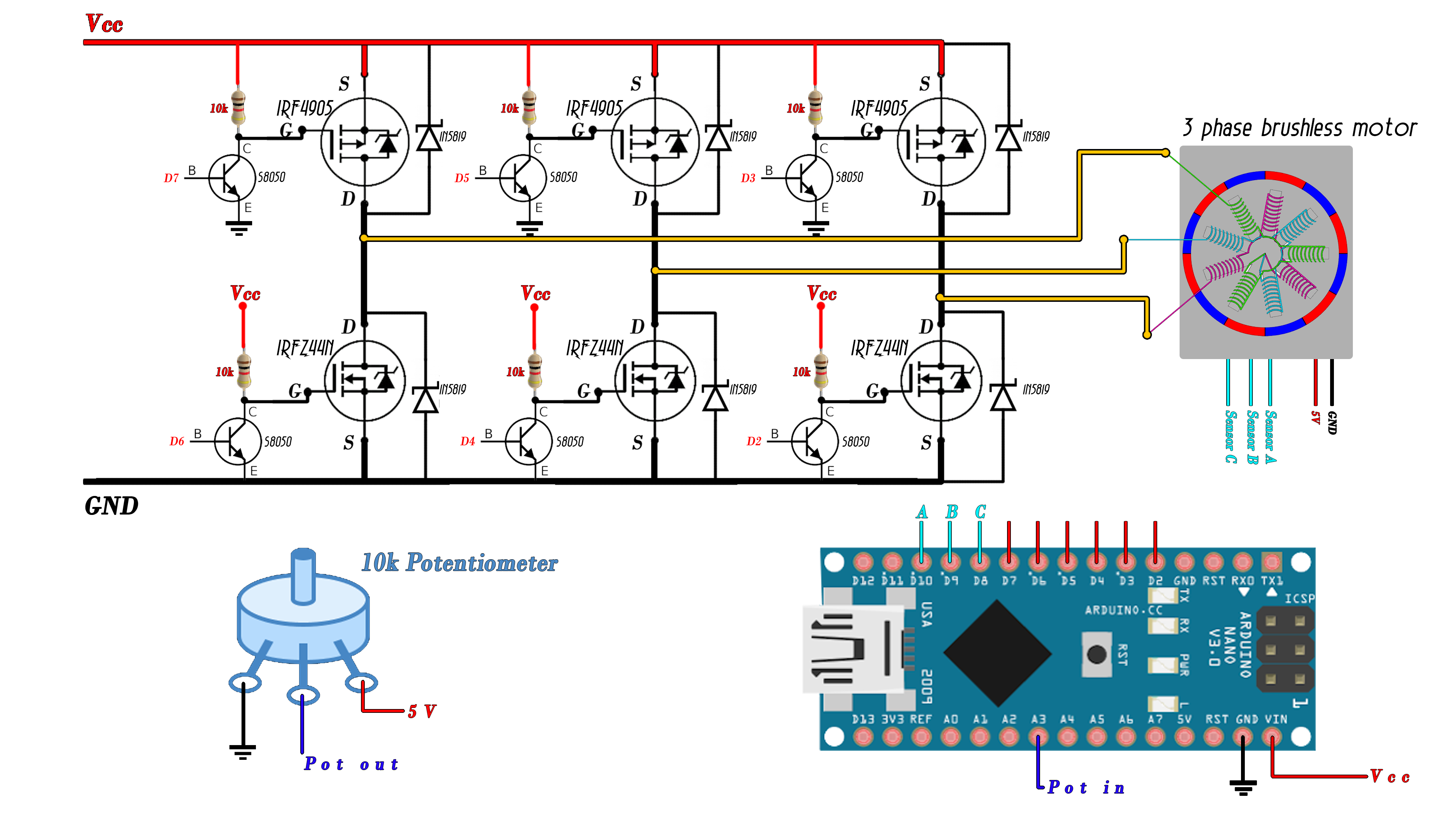
There are two types of brushless DC motors: sensored and sensorless. Sensored BLDC motor has built-in 3 hall effect sensors, these sensors detect the rotor position of the BLDC motor. Controlling a sensored BLDC motor is easy since we know the rotor position like what was done in the project below: Sensored brushless DC motor control with Arduino

Dc Motor Controller By Lithium Battery Wiring Diagram Wiring Diagram
Brushless Direct Current (BLDC) motors are one of the motor types rapidly gaining popularity. BLDC motors are used in industries such as Appliances, Automotive, Aerospace, Consumer, Medical, Industrial Automation Equipment and Instrumentation.